


Hydrocarbons in the Norne field are located in the Lower to Middle Jurassic sandstones, which are of a good reservoir quality. An oil zone 110m-thick, with an overlying gas cap, make up the hydrocarbon column.
The reservoir is a flat structure with the crest about 2,525m below mean sea level (MSL). Reservoir pressure is close to hydrostatic, with a formation pressure of 273bar and a temperature of 98°C at a reference depth of 2,639m below MSL.
Recommended White Papers
Recommended Buyers Guides
The oil / water contact is defined at 2,688m. Reserves in-place are estimated at one billion barrels (160 million cubic metres) of oil and 29 billion cubic metres of free and associated gas.
Reservoir simulations and risk analysis suggest that the most likely estimate for recoverable reserves is 450 million barrels of oil and 15 billion cubic metres of gas.
Production and storage
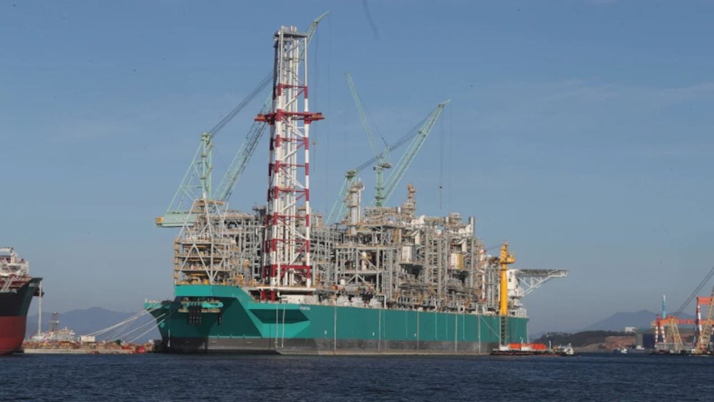
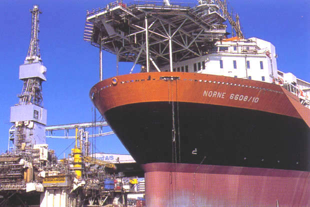
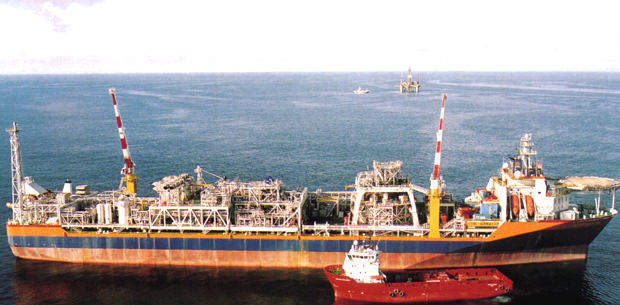
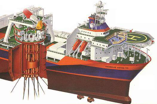
The production and storage vessel is a turret-moored monohull, which is equipped with production, storage and offloading facilities. Based on the Tentech 850 S design, it will weathervane around a turret attached to the seabed by a 12-point mooring system.
Processing facilities and power units are installed on deck, while oil will be stored in tanks in the hull before they are loaded into shuttle tankers through an offloading system located aft.
The processing and utility systems will be fabricated as skid-mounted units by various suppliers, mainly in Norway.
Topside production systems and equipment are due to be placed on a deck 3.5m above the ship’s cargo deck, so as to provide the air gap required for safety reasons.
These installations comprise oil separation and produced water treatment, gas separation and compression, power generation, water injection, export metering, chemical injection and a heating and cooling medium.
Main processing system
The wellstream will be transferred via the swivel mounted in the turret to the inlet separator, operating at 15bar-20bar. Oil from this separator is stabilised in a second separation unit, operated at 1.5bar-2bar, before it is transferred via a coalescer to a storage tank.
Gas from the second-stage separator is compressed in two stages, then mixed with gas from the inlet separator. All the gas is then compressed in three stages to 280bar for its reinjection into the reservoir.
Water injection
Deaeration of the injection water has been eliminated, since the presence of oxygen in the injected seawater is expected to stimulate reservoir productivity. Produced water will also be re-injected into the reservoir.
Together, with the reduced use of chemicals owing to the elimination of deaeration, this solution will help to safeguard the environment.
Injecting raw seawater, together with the produced water, has simplified the water-injection system, but has also required the extensive use of high-quality materials.
Subsea system
Subsea production facilities will comprise five well templates: three for production, one for water injection and one for combined gas and water injection. Each template has four slots and the capacity to tie in additional satellite wells. Flexible flowlines and risers are specified.
A multifunctional umbilical will be used to control and monitor the subsea system to distribute chemicals and hydraulic fluid, as well as to supply power. The templates are being installed in northern and southern groups, placed about 4,000m apart. Water depth varies between 370m-390m.
One production and one water-injection template will make up the northern group. These installations are tied back to the production ship by two 9in production lines, one 9in water-injection line and one control and service umbilical.
The southern group comprises two production templates, a combined water / gas injection line and two control and service umbilicals. The templates in each group are positioned so that the rig can enter all the slots without the need for anchor handling.