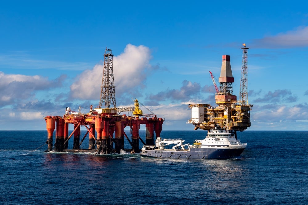
Changing operating conditions for floating production, storage and offloading vessels (FPSOs), floating storage and offloading units (FSOs) and regular transport ships have kick-started a debate over the cathodic protection needed for the hulls of this new class of vessel.
“One point I try to make is that the oil and gas industry should treat FPSOs and FSOs as if they are fixed structures when it comes to designing corrosion control systems,” says Mike Surkein, senior consultant for the materials selection and corrosion control group at ExxonMobil Development Company.
Go deeper with GlobalData

“Historically, the industry has viewed fixed platforms that were attached to the seafloor permanently as fixed offshore structures. Even if something is floating, it’s still an offshore structure. The industry makes a mistake when they view these systems as ships.”
Surkein considers the superior form of corrosion control for an FPSO/FSO hull to be a combination of coatings and cathodic protection. “The offshore industry has long-term experience selecting and applying hull coatings, so there is little controversy as to the type of protection to use other than whether to apply an anti-fouling coating or not,” he explains.
However, the optimum type of cathodic protection system to deploy remains a subject of some controversy. Because FPSO/FSO hulls resemble those of trading tankers, the cathodic protection system design approach used most often here also seems to be the first choice for FPSOs/FSOs – an impressed current system.
See Also:
According to Surkein, the objective of these systems is to minimise the number of anodes and reference electrode components while fully achieving the criteria for cathodic protection on the hull throughout the entire design life.
How well do you really know your competitors?
Access the most comprehensive Company Profiles on the market, powered by GlobalData. Save hours of research. Gain competitive edge.

Thank you!
Your download email will arrive shortly
Not ready to buy yet? Download a free sample
We are confident about the unique quality of our Company Profiles. However, we want you to make the most beneficial decision for your business, so we offer a free sample that you can download by submitting the below form
By GlobalData“Once a detailed review is conducted, you find that the size of the impressed current system, which includes a number of components, will end up greater than those deployed on tankers,” says Surkein, who also recommends that impressed current anodes are installed within a dielectric shield – normally fibreglass or epoxy – to protect the hull steel and paint system from excessive levels of protection in areas immediately adjacent to the anode.
At negative electrical potentials, degradation to hull coatings and hull steel is possible due to the byproduct of hydrogen in these conditions. Thus, Surkein suggests that during the impressed current system design, the anode quantity and locations should be predetermined so that they can be installed without interfering with hull fabrication to then produce the appropriate electrical potential – not an electrical (negative) potential that will cause long-term issues – and also
so that they may be replaced during the design life.
Impressed current cathode system
ExxonMobil installed a large fixed structure in an Arctic environment that required a unique, first-of-its-kind impressed current cathodic system. A galvanic anode system could not be used because the yearly cyclic freezing conditions would have likely damaged the anodes to be installed on the structure’s external surfaces.
The impressed current system deployed by ExxonMobil in the Arctic included buried steel or concrete containers that held the impressed current anodes connected to the power supply by robust electrical cables. Burial was needed to protect the anodes and cables from ice scour. The impressed current system included numerous reference electrodes installed around the structure.
Surkein believes the key to achieving effective corrosion control during the entire design life is the quantity and location of anodes, the number of reference electrodes and their ability to continually and accurately measure hull potentials, the size and location of dielectric shields, and power source operation.
“With regards to galvanic anodes, the offshore industry is quite familiar with design and monitoring requirements, as this type of anode has been used successfully for fixed offshore structures since the inception of the industry,” he points out.
There are internationally accepted codes that provide guidance for galvanic anode system design. No permanently installed reference electrodes should be required.
The galvanic anode materials used, normally alloys of aluminium, produce an electrical potential in the range needed for cathodic protection. Galvanic anodes cannot produce electrical potentials in the unwanted range, so no hull coating or steel impact should be expected.
Therefore, the use of galvanic anodes is simple and they should require no maintenance, just periodic monitoring in accordance with local regulations, which usually means annual surveys.
Maintenance options
One clear difference between the two types of cathodic protection systems is the level of maintenance required. Impressed current systems need more frequent monitoring, usually monthly or quarterly.
Component life is normally less than design life, so repairs and replacement are a consideration. Power supply is active, so inspection and maintenance is required.
Each anode and reference electrode needs individual cables. Trained staff are required on the vessel to interpret the monitoring data and make necessary adjustments.
Normally, the system should be turned off when divers are in the water around the vessel.
Galvanic anode systems typically require no maintenance. The anodes are usually installed and distributed along the entire hull.
These systems require periodic monitoring, normally yearly, in accordance with local regulations. Anodes are designed for the entire life and do not need replacement.
There is no active power supply, no cables and periodic visits to the vessel by trained staff will take care of the monitoring.
Results from design calculations indicate that the galvanic anode design is the optimal method for hull protection. “It’s easy to reach this conclusion when you look at factors such as ease of installation, cost, operational and maintenance needs and performance,” says Surkein.
He explains that galvanic anodes are simply welded to the hull directly or via a doubler plate. The work can be completed easily during block fabrication for new construction or refurbishment in the shipyard, in the case of a retrofit.
Galvanic anode installation is wholly external to the vessel, and the only major issue is likely to be scheduling difficulties. The welding work needs to be completed prior to internal tank coating if no doubler plates are used.
If doubler plates are used, then the fact that the anodes are welded to the plate means there should be no impact to the tank coatings, and therefore no coating schedule impact. When the hull is coated, the anodes should be covered so they are not painted. The galvanic anodes are usually distributed around the hull.
“In my experience, a galvanic anode cathodic protection system is typically less expensive than a properly designed impressed current system,” says Surkein. “This makes sense when you consider that each impressed current anode and reference electrode needs its own cable that terminates at the control centre of the system, normally the vessel control room.
That could mean there may be thousands of metres of cable all in conduit running within the vessel. The main performance issue is that with an impressed current system, there are concerns about coating and steel impact due to hydrogen charging.
These issues can be controlled, but it requires experienced hands on the vessel to monitor the system. Galvanic systems should have no possibility of impacting the coating or steel performance.”
A galvanic anode system can be easily designed to provide adequate cathodic protection for the entire design life without the need for maintenance or repair. It is unlikely that an impressed current system could provide similar long-term performance without maintenance or repair.
Surkein says this is especially true for the typical long design lives of today, which aim for 25 years and beyond.
Sakhalin-1
The Sakhalin-1 Project is an oil and gas development located on the north-east shelf of Sakhalin Island, a Russian territory in the north Pacific, which was declared commercial in late 2001. The project area includes the Chayvo, Odoptu and Arkutun-Dagi fields. Exxon Neftegas Limited, an affiliate of the US Exxon Mobil Corporation, is the operator of the project. Other consortium members are two Russian companies: Sakhalinmorneftegas-Shelf and RN-Astra, as well as Japanese firm Sakhalin Oil
and Gas Development Company, and India’s ONGC Videsh.
Sakhalin’s total recoverable reserves are thought to be in the region of 2.3 billion barrels of oil (307 tonnes) and 17.1ft3 trillion of natural gas (485m3). The first phase of the Sakhalin-1 project, one of the world’s most ambitious developments, reached peak production of 250,000 barrels of oil per day in the first quarter of 2007.
The weather at Sakhalin Island is severe. Winter can span from five to seven months and temperatures plunge as low as -45°C. There are dangerous storm winds, severe waves, icing of vessels (for up to half the year), intense snowfall and poor visibility due to coastal fogs.
Weather issues
Very cold and freezing operating conditions, such as those experienced at the Sakhalin-1 project in the North Pacific, affect the need for corrosion protection. Surkein points out that FPSOs/FSOs are normally installed in water environments.
Corrosion is always an issue, because of the generally low seawater temperatures.
“Keep in mind that for normal deepwater conditions, of 1,000m or so in depth, seawater temperature is only around 4-7°C, so corrosion is something you need to get to grips with as a matter of routine,” he says, pointing out the necessity for more powerful systems in these colder conditions.
“Going by industry standards, more cathodic protection design current is needed at cold Arctic water temperatures (less than 7°C at the typical vessel depth of less than 30m) than specified at warmer temperatures.”
But, freezing conditions call for special attention. “The waters we’re talking about are not frozen all-year round, but the freezing conditions should be considered when choosing the anode type and locations,” says Surkein.
“Ice can be physically aggressive and the design should be robust enough to ensure that the ice condition doesn’t damage the anodes. When exposure conditions are so aggressive, a custom-designed solution is the most sensible option.”