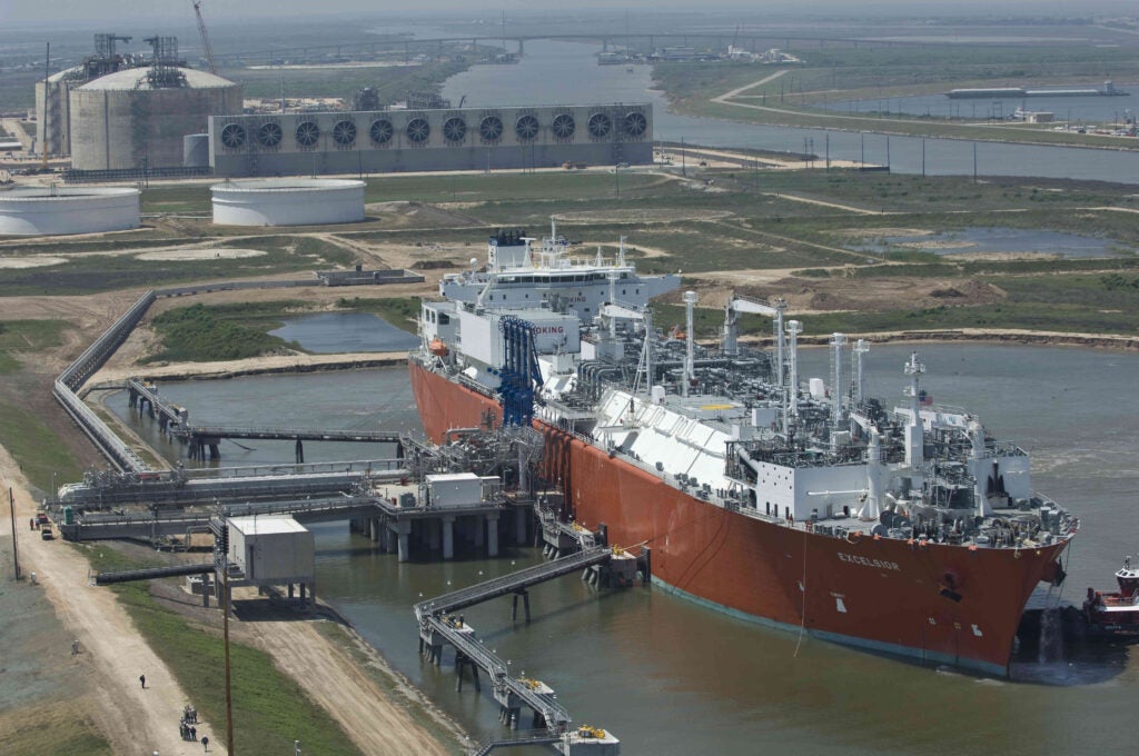
StatoilHydro operates around 1,000km of offshore multiphase pipelines. The deployment of multiphase transport has gone through tie-backs for low gas to liquid ratio (GLR), oilfields (Gullfaks/Åsgard) in close vicinity to offshore facilities (<5-10km), tie-backs of high GLR gas condensate fields (Åsgard) of moderate distance (40-50km) and to 70-140km long transport lines of partly processed (Troll, Huldra and Kvitebjørn) and unprocessed well stream (Mikkel, Snøhvit and Ormen Lange).
The gas condensate lines have been designed based on the same main philosophy, which has been to select a line diameter that keeps the flow well within the friction-dominated flow regime (low liquid accumulation in line) for the normal operational range and to have strict procedures for liquid control. This design philosophy yields fairly small pipe diameters and high pressure drops, deemed necessary due to the large uncertainty of the prediction tools when liquid starts accumulating in the line (approaching gravity-dominating flow).
Each development has provided experience that has been used to develop the design and operation of new gas condensate lines. As many future large gas condensate discoveries will be at increasing distances from shore or existing processing facilities, there is a drive to increase the transport distance further.
New design procedures, with the main objective of minimising the required export pressure for the transport system, must be developed. A low pressure drop is achieved in large diameter lines.
However, this will give extensive liquid accumulation at turndown rates, and the accumulation will give restrictions with regard to operation. Therefore, the final diameter selection is a compromise between pressure drop, liquid accumulation and their uncertainties.
See Also:
Minimising the export pressure would have the following key advantages:
How well do you really know your competitors?
Access the most comprehensive Company Profiles on the market, powered by GlobalData. Save hours of research. Gain competitive edge.

Thank you!
Your download email will arrive shortly
Not ready to buy yet? Download a free sample
We are confident about the unique quality of our Company Profiles. However, we want you to make the most beneficial decision for your business, so we offer a free sample that you can download by submitting the below form
By GlobalData- The drilling of new wells required to maintain the design production rate may be postponed.
- Pre-compression at the inlet plant can be avoided or postponed.
- The period without on-field compression will be prolonged.
- Installation of more lines can be avoided or postponed.
- The economical feasibility of the development will be enhanced.
Design procedures
For gas condensate systems (low liquid fraction fluids), the liquid will have a tendency to accumulate in the steeper uphill segments along the pipeline for low rates. The pressure drop will be influenced by the hydrostatic pressure drop of the liquid: gravity-dominated flow is seen.
For higher rates, liquid accumulation will be low and the pressure drop is dominated by friction. The accumulation increases with an increase in pipe diameter as the gas velocity decreases.
Also, the liquid accumulation is highly dependent on the pressure level in the line. The minimum pressure drop for a gas condensate line occurs at a rate close to onset of severe liquid accumulation.
The uncertainty of the design tools increases as the rate decreases and approach conditions for severe liquid accumulation and gravity dominated flow. The design tool used by StatoilHydro is OLGA.
For long and ultra-long gas condensate lines, the current design practice would give a large pressure drop. A fairly small line diameter would be selected to ensure friction dominated flow and low liquid accumulation.
The pressure level at the field would be high, making it difficult to keep sufficient drag on the liquid to overcome the gravity in the steeper uphill pipe segments. Gravity-dominated flow (high liquid holdup) may occur for a large part of the line.
The non-uniform transport conditions along the line due to the variation in pressure will be more dominant as the length of the line increases. As a consequence, different approaches should be used for design of long (<200-300km) and ultra-long (>200-300km) gas condensate lines.
The lengths of long and ultra-long lines are only indicative, and they should be evaluated for each development case. The key objective of the new design procedures for long gas condensate lines is to minimise the pressure drop.
This is achieved by selecting a large pipe diameter and allowing operation in the gravity dominated region for parts of the line. The main steps in the new design procedures are:
Decide the normal operational envelope (production range between a maximum and a minimum rate for which extended operation at steady conditions should be allowed).
Minimise the pressure drop for production in the normal operational range by selecting a fairly large pipe diameter that gives a pressure drop close to the minimum pressure drop.
At the design rate, friction-dominated flow should be dominant.
Accept relatively large liquid inventory. That is, allow operation in the gravity dominated regime for parts of the line.
Exploit the pipeline’s slow response to transients to reduce slug-catcher size.
For production variations, take into account the long accumulation and transport time for liquid in the line and the drainage from the slug-catcher.
Pigging for liquid control and inspection. Introduce special procedures if required.
Optimise slug-catcher and receiving facility design.
If possible or required, alleviate liquid accumulation in line by: optimising the pipeline route, introducing dual lines/cyclic pipeline operation and/or introducing outlet compression to reduce pressure level and enhance liquid transport.
For ultra-long lines, the design procedure is mainly as described for long lines. The main difference is related to pipe diameter selection.
For ultra-long lines, the flow conditions will vary largely along the line. An optimum design would keep uniform flow conditions with regard to liquid transport along the line.
This can be approached by using multi-diameter lines, for example, pipes of different diameters are used for segments of the line. Large pipe diameters are used for segments close to the processing plant where the pressure is low, keeping gas velocity at a moderate level to reduce pressure drop.
Near the field, where the pressure is high, small diameters are used to keep the gas velocity sufficiently high for efficient liquid transport.
Field data collection
It is important that the field data applied are of good quality. StatoilHydro does comprehensive work to collect its own field data.
There is still not a large amount of field data available to the public for gas condensate lines. Most data are kept within the oil companies.
However, some data for comparison with OLGA predictions are available through the OLGA Verification and Improvement Project (OVIP) run by Scandpower PT for the participating parties.
The data are kept anonymous by plotting against a normalised gas velocity derived from a scaled dynamic gas pressure at the pipeline outlet. The dynamic pressure is the governing parameter describing the flow in the friction dominated region, together with superficial liquid velocity and pipe diameter.
The diameter effect on flow and pressure drop is well modelled by the hydraulic diameter concept and use of Moody’s formula to calculate the friction factors. As the gas rate decreases and gravity dominated flow is experienced, other parameters are required to describe the multiphase flow.
As a result, more parameters must be compared for the field cases and the case under design in order to establish the relevance of the field data.
The liquid content measurements for gas condensate lines are usually taken from pigging or rate variation operations. These measurements require good control of slug-catcher liquid levels and liquid outlet rates during transient conditions in order to be accurate.
Usually the production systems are not instrumented to allow for direct and accurate measurements of the condensate and the water/inhibitor rates and levels.
A new measuring method, which can be applied without interfering with operations, has been developed by StatoilHydro in collaboration with the Institute for Energy Technology in Norway. Tracers are injected at the inlet of the line.
The inventory for each liquid phase is calculated from the measured tracer transport time through the line under steady production. For calculation of the best estimate of the liquid inventory, the different transport mechanisms for the liquid are taken into account.
Therefore, partitioning tracers, designed to mimic the transport of a typical component in the liquid phase, are used. For the condensate phase, the tracer will be both in the gas and the condensate phases.
Due to condensation, some of the partitioning tracer in the gas, as the heavy HC-components of the produced fluids, will drop out along the line. In case of no flashing the liquid inventory is simply calculated as the tracer transport time multiplied by the liquid volume rate at the pipeline outlet.
Model comparison and tuning
A brief introduction to field data work was done for StatoilHydro-operated gas condensate flowlines for prediction uncertainty assessments. Field measurements were collected from several gas condensate lines.
Among these are the Troll-Kollsnes pipeline, the Huldra-Heimdal pipeline, the Kvitebjørn pipeline and the Midgard pipelines on the Åsgard field. Most of the liquid inventory measurements have been taken with the tracer method.
For the Troll pipeline, measurements are also collected from pigging operations.
In general, the pressure drop predictions by OLGA for friction dominated flow compare well to the measured field data, usually within +-10%.
However, at the lower rates, where gravity dominated flow occurs, the uncertainty is larger. This is mainly explained by the failure of OLGA to predict the onset for severe liquid accumulation correctly.
Comparisons of OLGA with field measurements show that OLGA usually gives a large under-prediction of the onset gas rate for liquid accumulation (15-40%), which leads to an under-prediction of the liquid content at the low rates. For high rates, there may be both under- and over-predictions of the liquid volumes.
The uncertainties in the prediction of the distribution between condensate and water/inhibitor can be very large (+-50-100%).
For low liquid fraction fluids, the onset rate for liquid accumulation is generally under-predicted for the field data and over-predicted for the experimental data. One explanation is that the OLGA multiphase flow correlations do not include models for the effect of the interface turbulence transfer and waves on the liquid layer velocity profile.
When the OLGA closure laws are correlated against small scale experimental data, the interface friction is increased in order to compensate for the effect of the turbulence and the waves on the liquid layer. For large pipe diameters, the effect of the turbulence and waves at the interface will be less dominant than their effect in a small diameter pipe.
The interface friction in OLGA will likely be too large, and the liquid transport too efficient in a large diameter pipe. This will give an under-prediction of the onset rate for liquid accumulation for large pipe diameters.


