
Gullfaks South, Rimfaks and Gullveig lie in block 34 / 10, in a water depth of 135m. The Gullfaks Satellites produces around 260 million barrels of recoverable oil and condensate in the first phase. Production plateaued at 125,000 barrels per day.
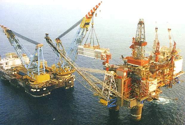
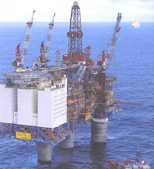
The project has been developed with three substantial production platforms namely Gullfaks A, Gullfaks B and Gullfaks C. Oil and gas is sent to platforms A and C from platform B for processing, storing and further export.
Recommended White Papers
Recommended Buyers Guides
Oil from the platforms is transferred to shuttle tankers. Gas from the platforms is transferred via the Statpipe trunkline for further processing at Kårstø north and then exported from there.
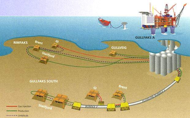
Another three satellite fields – Gullfaks South, Rimfaks and Skinfaks and Gullveig – were developed. Gullfaks A and C platforms remotely control these fields.
A contract for time limited modifications capacity services for the development of the field has been given to Aibel AS in March 2010.
Gullfaks reservoirs
Gullfaks South, Rimfaks and Gullveig lie to the south and southwest of the main Gullfaks field. All three fields produce from the Brent group of sands, while Gullfaks South and Rimfaks have reserves in the Statfjord formation. The depth to the top of the reservoirs ranges between 2,500 and 3,000m below sea level. The reservoir temperature is 97°C and initial reservoir pressure is at 370-470bar.
Discovered in 1979, Gullfaks South contains oil, gas and condensate (light oil) in two formations. Rimfaks was proven in 1983 with oil, gas and a high-condensate content.
Oil as well as small quantities of associated gas were established in a separate structure in 1995.
Proven in 1995, Gullveig contains oil with small quantities of associated gas. These reservoirs are very complex, with several thin oil layers. Large volumes of gas must be handled when recovering the oil.
Gullfaks development
Phase I of the Gullfaks satellites development received the green light from the Norwegian authorities in March 1996, just a year after the latest discovery was made, and came onstream in 1998. It embraces oil and condensate production from the three fields, with gas reinjection.
The second phase was approved in 1998 by Norwegian authorities and came onstream in 2001. This phase includes production of the gas and related liquids with subsea installations tied back to Gullfaks A and Gullfaks C.
Platform modifications
Gullfaks A will be modified to increase its capacity for gas treatment and reinjection.
Two new modules are being installed, one measuring 39x12x15m for gas treatment and the other measuring 16x10x12m for pipeline pigging.
The total weight to be handled is about 6,500t. These units will, as far as possible, be completed and tested on-land to reduce offshore work.
An $8.7m FEED study contract for upgrading the drilling facilities of platform A was awarded to Aker Solutions in October 2009. The study is expected to be completed by April 2010.
Subsea details
Eight subsea templates with a total of 31 available well slots were planned for phase I. Wellstreams were tied back to Gullfaks A, with gas being returned for reinjection into the reservoirs. In total there are 23 wells, including six for gas reinjection.
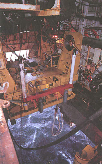
In close collaboration with the Norwegian subsea technology specialist Kongsberg Offshore, Statoil developed a special hinge-over subsea template (HOST), which can be installed from a rig.
With four well slots, this unit provides opportunities to connect flowlines and control umbilicals onto two opposing sides. Additional templates can be tied in at a later stage. The subsea production system was designed to permit the installation of a multiphase meter on each well.
All subsea work in the satellites project were carried out without diver intervention. Flowlines were tied back to the templates with the aid of the underwater tie-in system (UTIS).
Gullfaks flowlines
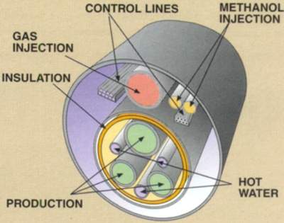
Wellstreams from Gullfaks South will be transported through flowline bundles that can be warmed with hot water to avoid hydrate formation and wax deposition in the event of a shutdown. About 3MW of waste heat is available from the gas turbines on Gullfaks A for this purpose.
Developed in collaboration with Rockwater, the solution yields a double environmental benefit using free waste heat for a useful purpose while reducing the use of chemicals. The two bundles were produced by Rockwater, in their full length of several kilometres, on railway tracks in Scotland.
Making the flowline out of stainless 13% chrome steel also reduced the need for chemical corrosion inhibitors.
The $20.8m contract for the tie-in was won by a joint venture between Rockwater and Stolt Comex. Work will be carried out by the DSV Seaway Osprey. Work at Gullfaks A will be carried out by divers.