
Interest in heavy oil production has increased in recent years because of the large reserves that are accessible. Estimating world reserves is difficult, but the total volume of heavy oil available is probably about the same as that of conventional oil.
However, a major difficulty with heavy oil is its extremely high viscosity, which makes it difficult to extract. So one key factor in facilitating the production and transportation of the hydrocarbon phase of heavy oil is the ability to decrease its viscosity.
Go deeper with GlobalData

Discover B2B Marketing That Performs
Combine business intelligence and editorial excellence to reach engaged professionals across 36 leading media platforms.
High-viscosity oil has a weak flow rate which often makes its exploitation uneconomical, so heavy oil production requires some way of increasing the flow rate. Heating the oil, using hot vapour injection or in-situ combustion, has been proposed as a method of decreasing viscosity in the field, but high viscosity also makes pipe transportation difficult.
The simple single-phase flow of heavy oil in a tube will lead to a huge pressure drop that makes pumping impossible. Several solutions have been proposed to solve this problem. Dilution of the heavy oil in a lighter phase is the most common way to reduce friction.
However, light oil is then needed in very large quantities and recycling capacity needs to be built. Light oil is separated at the treatment plant, and a second, parallel pipe transports it back to the field. The requirement for light oil is a major limitation of this technique.
NEW APPROACH
At the Institut Français du Pétrole, we have investigated experimentally the core annular flow (CAF) transport solution. CAF is a flow regime where the oil phase runs through the centre of the oil transportation pipe while water flows next to the pipe wall surface.
An attractive characteristic of this flow is that the pressure drop is close to that of pure water and relates only weakly to heavy oil viscosity. This remarkable phenomenon was observed long ago, and there has been industrial interest in it for around a hundred years. A 1904 patent of Isaacs and Speed in the USA first mentioned the technique of transporting viscous product using ‘water lubrication’.
Despite this early interest, a large-scale industrial pipeline for heavy oil was not built until the 1970s, when a 38km long, 15cm diameter Shell pipeline was constructed near Bakersflield in California. For more than ten years, a viscous crude oil has been produced at the flow rate of 24000bbl/d using a water-lubricated regime.
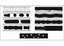
Several flow regime configurations are possible when flowing a mixture of water and oil in a tube (see Figure 1). Multiphase flows of liquid-liquid and gas-liquid are crucial in the oil and gas industry and a lot of work is available on flow regime characterisation.
Figure 1 shows various flow regimes when oil and water are flowing together in different ratios. The configurations depend on the fluids’ properties, such as their density and surface tension, and also on the shear rate in the flow. Mean injection velocities are also key parameters for flow regime determination.
Figure 1 represents the different configurations obtained when varying the relative amount of oil in the water, for a fixed injection flow rate. An emulsion of small droplets is found where the quantity of oil in water is low. If more oil is added, the droplets grow to the size of the pipe radius and oil slugs appear in the water phase.
As yet more oil is added, these slugs merge and the oil phase becomes continuous along the pipe. Stratified flow and a CAF regime are observed under these conditions. When the oil fraction gets close to one, a continuous oil phase with water droplets is seen.
CAF REGIME
The CAF regime provides the lowest pressure drop of all the flow regimes. In this regime, water at the pipe surface lubricates the oil core. Perfect CAF is shown in Figure 2. A small water layer is sheared and the velocity field is approximately linear if the difference in viscosity between the oil and the water is large. In such a case, the oil core is nearly a plug flow. Very weak deformations take place.
Perfect CAF appears to be very rare and can exist only for density-matched fluids. Observations have shown that waves are usually created at the water-oil interface, leading to wavy core annular flow (WCAF). This type or CAF seems to be the one seen in real situations.
With fluids that have a different density, a buoyancy force causes a radial movement of the core. If no counterbalancing force is applied, the buoyancy effect pushes the core to the upper wall of the pipe. It has been shown that waves at the interface are necessary to create sufficient lubrication force to counterbalance the buoyancy force. The mechanisms that lead to the formation of such waves at the interface are not yet completely understood.
Many authors have investigated the stability of the CAF system. Because of its simplicity, the perfect CAF without any density difference was first analysed. It has been shown that perfect CAF stability is achieved for only a small range of parameters. With a fixed volume ratio between oil and water, the CAF is not stable at low velocity. Capillary instability, due to surface tension, appears and breaks the core.
However, an increase in velocity reduces capillary instability and the flow regime can then be observed. With a larger velocity, perfect CAF flow again becomes unstable. Due to interfacial friction, undulation of the flow occurs, leading to WCAF, although this configuration can stabilise again. Only much higher velocities can break up the core or the emulsification process. The velocity range of CAF is shown in Figure 3.
The range of stability raises two main problems in terms of industrial development. First, the operating conditions (pump power, pipe geometry and so on) must be compatible with the stability of the flow; and second, as CAF is not stable at low velocity, the problem of stopping and starting the flow must be addressed.
Despite the problems mentioned above, a huge advantage of CAF is that it has the smallest pressure drop of all the two-phase flow regimes. The transport of highly viscous crude oil is possible with a pressure drop almost as low as that of water. Figure 4 shows the pressure drop variation with flow rate for different transportation systems. The very low pressure gradient with CAF has drawn much interest from various industries that deal with viscous paste.
INDUSTRIAL DEVELOPMENT
A 55km CAF pipeline has been used to transport highly viscous bitumen produced in the area of the Orinoco belt in Venezuela. Studies of this pipeline have demonstrated the capacity of this technique to transport heavy oil on an industrial scale.
The technique has its problems. Restart conditions do not fall within the annular flow regime and the restart pressure can be high. Also oil can adhere to the wall in flow conditions, while the pipe section can be restricted, and an increase in pressure drop and even blockage can be observed.
Different solutions have been proposed to overcome these difficulties, such as the treatment of the pipe inner surface with cement. However, the unusual
behaviour of CAF has meant the technique is not widely used in the oil transport industry.
EXPERIMENTAL WORK
The installation used to perform our experiments consisted of a flow loop (see Figure 5) comprising a heavy oil storage tank and a stainless steel pipe (12m long and 25mm in internal diameter) equipped with a fluid lubricant injector specially designed for pipe-wall lubrication and a data acquisition system.
The heavy oil, stored in a 450l tank, is transferred using a screw-type positive displacement pump to the centre of the injector (see Figure 6) located at the
head of the pipe. The flow rate is controlled by varying the speed of the pump. Water is drawn from a 50l stainless steel tank and pumped into the annulus of the injector using a volumetric pump, to lubricate the internal pipe wall.
Pressure drops within the pipeline are measured across a 6m long test section equipped with two pressure sensors. A recording system connected to a computer allows the recovery of the pressure sensor’s signal and the control of the pressure across the test section in real time. The test procedure essentially consists of following in real time the variation of the pressure drop of the heavy oil flow with and without lubrication to observe the behaviour and the efficiency of the lubrication process along the conduct.
PROMISING RESULTS
In our experimental investigation into the technique of lubricated flow, heavy oil was injected into the centre of the pipeline, while a thin water film was injected around it. When the water was injected, the flow converged rapidly to CAF regime and remained stable. The flow rate of water is a fixed ratio of the oil flow rate. Pressure measurements showed a reduction of more that 90% in the pressure drop with lubrication.
One very curious observation was made: a decrease of the pressure drop with increased flow rate. To estimate the reduction in the pressure drop, the pressure drop in the case of perfect CAF was calculated, and a large discrepancy was found between this calculation and the experimental result.
A simple phenomenological model was then proposed to take into account the density difference between oil and water. The buoyancy force tends to lift the core at the top of the tube and the lubrication process tends to centre it.
Competition between these two mechanisms leads to eccentric positioning of the core, and a small part of the oil core touches the wall, leading to a pressure drop. Empirical study of the oil-water perimeter suggests that pressure reduction is dependent on the oil flow rate. The huge reduction in friction inside the pipe that the lubricated technique produces has generating great interest in this technique for the transportation of heavy oil.
Steady-state flow has been demonstrated in this study, and the pressure reduction can reach 95% for some flow parameters. However, stop and restart still have to be studied before the technique becomes feasible on an industrial scale.
