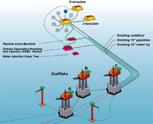
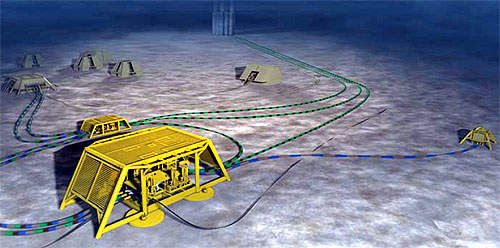
Tordis is located in block 34/7 of the Tampen area in the Norwegian North Sea. It came on-stream in 1994. In addition to the main Tordis structure, the development embraces the Tordis East (1998), Borg (1999) and Tordis South East (2001) fields. These discoveries have all been developed with subsea installations tied back to the Gullfaks C platform 10km away for processing, storage and export.
The field is operated by Statoil 28.22% on behalf of Petoro 30%, Hydro 13.28%, Esso 10.5%, Idemitsu 9.6%, Total 5.6% and RWE-DEA 2.8%.
Recommended White Papers
Recommended Buyers Guides
After the main Tordis manifold was installed to receive seven satellite wells, templates J (production) and K (injection) were installed. The field currently has nine producing wells, originally producing 24,000bpd but falling back to 12,000bpd along with six injectors to maintain reservoir pressure.
STATOIL OPERATION
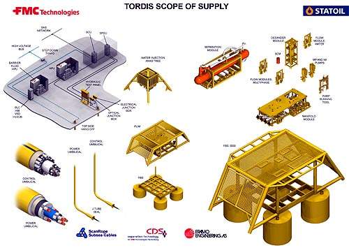
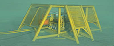
In December 2005, Statoil received government approval for its Improved Oil Recovery (IOR) project. It awarded the NOK625m contract to Kongsberg FMC for a subsea separation station. Acergy won the NOK200m contract for marine operations while Saipem will lift the separation station into place under a NOK50m contract.
Statoil expects to improve the field’s recovery factor from 49% to 55% or around 35 million barrels of oil, accounting for approximately 19 million barrels of the oil recovery.
This will be achieved by removing water from the well stream and reinjecting it in a separate well, thereby reducing the back pressure towards the Tordis field and allowing more hydrocarbons to be processed at Gullfaks C.
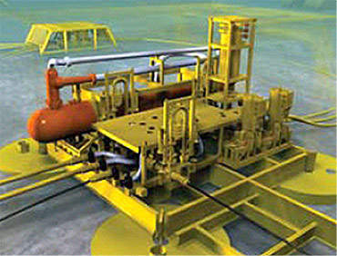
The well fluid is first routed into the separation tank to remove the gas. The remaining water, oil and gas are separated through the gravity. The water is pumped via a water injection pump directly back into the Utsira reservoir through a 12in ball valve Christmas tree.
PUMP AND SEPARATION SYSTEMS
The water injection pump is a standard Framo pump system which is driven by an electrical motor powered through an electrical power cable from the Gullfaks C platform. The pump can be retrieved for maintenance by a separate pump running tool.
Oil and gas are remixed and pumped through a standard Framo multiphase pump back to the Gullfaks C platform.
Sand deposits at the bottom of the separation tank. The sand management system has been designed to handle high amounts of sand (50kg to 500kg a day). A flushing system with specially designed nozzles will remove the sand at certain intervals into the de-sander module where it can be remixed with the injection water and reinjected into the reservoir downstream of the water injection pump. Alternatively, the sand can be remixed with the oil and gas flow and pumped back to the Gullfaks C platform.
The subsea separation station is equipped with two multiphase flow meters (Roxar) which will measure the composition of the well flow to prepare the separation system settings. A level monitoring system is installed in the separation tank to monitor water, oil and gas interfaces which again provides input to the speed of the water pump and the multiphase pump.
The manifold module interconnects the various modules to the flowlines via Rovcon connection system.
The assembly also includes a Pipeline Inline Manifold (PLIM) which allows full bypass of the subsea separation system. Other parts of the project include around 12km (seven miles) of control umbilical, 12km (seven miles) of power umbilical topside high-pressure units for pumps and control system, topside power to pumps subsea and a topside process control system.