

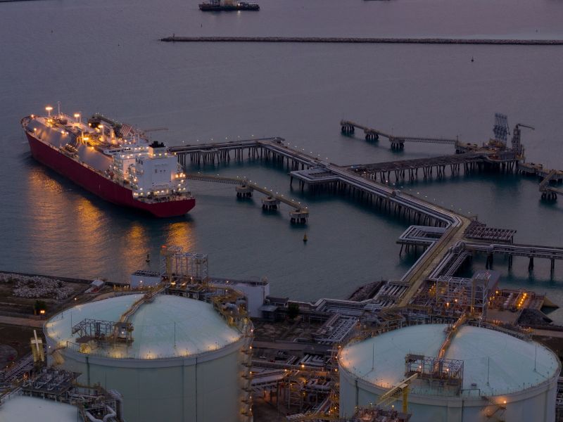
The ST LNG deepwater port project encompasses the construction of an offshore liquefied natural gas (LNG) export terminal in Matagorda Bay, Texas, US.
Privately held energy infrastructure company ST LNG is developing the project. Planned for execution across four sequential phases, the project involves an estimated investment of approximately $8.2bn.
Recommended White Papers

Recommended Buyers Guides

The US Maritime Administration (MARAD) approved the licence application for the scheme in October 2026.
Work on site is scheduled to begin in 2027, with the initial phase anticipated to enter commercial service in 2029.
The development is projected to support up to 2,000 jobs during construction alongside up to 855 permanent positions once operational.
ST LNG deepwater port project location
The ST LNG deepwater port export facility will be situated within federal waters of East Matagorda Bay, approximately 10.4 nautical miles off the coast of Matagorda County in Texas. Water depth across the project location ranges from 68ft to 72ft (20.7m-21.9m).
ST LNG deepwater port details
Planned for staged implementation, the terminal will provide a cumulative liquefaction output of 8.4 million tonnes per annum (mtpa).
Each of the four phases will comprise five fixed offshore platforms, a dolphin mooring installation consisting of three berthing dolphins and six mooring dolphins, interconnecting transit bridges, and a permanently moored floating storage unit (FSU). Separated by roughly 2,260ft, the four phases will operate independently.
Processed fuel will be transferred into the FSU at a nominal rate of 6,000m³ per hour.
Offloading operations will service LNG carriers with cargo capacities between 125,000m³ and 180,000m³, reflecting an average vessel size of 146,000m³. Factoring in loading velocities and berth occupancy schedules, the terminal will accommodate up to 25 vessels per phase each year, representing an annual turnaround of 100 vessels across the complete facility.
Offshore platform details
The project will encompass 20 fixed platform structures, split into five dedicated installations for each of the four phases.
Each platform will comprise a gas treatment platform, a liquefaction platform, a bridge support trestle platform, an LNG transfer platform, and an accommodation and utility platform.
A network of 16 link bridges, arranged as four structures per phase, will join the platform modules, while an FSU will attach to each bridge support trestle platform by means of a telescopic gangway.
The bridges provide walk-to-work transit for crews, establish emergency evacuation routes from manned sections, and support electrical cabling that distributes generation capacity to plant equipment across each stage.
These bridge walkways will also support piping assemblies that carry conditioned feed from the gas treatment platform to the liquefaction platform, followed by the transfer of liquefied fuel across the bridge support trestle platform to the LNG transfer platform for FSU bunkering.
Gas treatment platform details
Each development phase will feature a gas treatment platform engineered to condition 330 million cubic feet per day (mcf/d) of pipeline gas to meet liquefaction parameters.
Incoming feed gas will flow through a high-integrity pressure protection system before entering the processing train. Every platform will incorporate a three-deck structure measuring 230ft × 250ft.
Processing will proceed through four continuous stages, including mercury removal, acid gas sweetening via a closed-loop amine solvent wash, gas dehydration combined with heavy hydrocarbon (C5+) separation, and feed compression.
Liquefaction platform details
The ST LNG deepwater port project will incorporate four liquefaction platforms, dedicating one installation to each development stage. Every platform will house a single processing train rated at 2.1mtpa, receiving treated dry gas from the neighbouring treatment module. The entire terminal will deploy Chart Integrated Pre-cooled Single Mixed Refrigerant (IPSMR) liquefaction technology.
Each liquefaction system will include a perlite-insulated cold box containing the liquefaction heat exchanger, mixed refrigerant (MR) cold separator, and control valves, supported by two MR compression arrangements. Refrigeration duty will be provided by centrifugal MR compressors driven by two parallel-string gas turbines.
Every compressor unit will integrate two back-to-back sections to accommodate intercooling, mitigating discharge temperatures while raising operating efficiency. Four turbine-generator sets on the gas treatment platform will supply primary site power, supported by two essential power generators installed on the liquefaction platform.
LNG transfer platform details
Each phase will include one LNG transfer platform measuring 66ft × 46ft. Personnel will access the platform via a permanent pipe bridge extending to the bridge support trestle platform, while a gangway will provide access to and from the FSU.
The platform equipment will comprise a gangway, two firewater pumps, an LNG transfer monitoring station, and a storage locker for spare transfer hoses. Each platform will also have an LNG spill containment trough to collect spills and direct them overboard.
The LNG transfer platforms will generally operate without personnel, unless for maintenance activities.
Accommodation and utilities platform
The project will include four accommodation and utility platforms, with one platform installed in each phase. Each platform will provide accommodation for 100 people and include a 40ft × 40ft helideck.
Supporting facilities will include a 52ft × 23ft workshop and warehouse, a raw diesel treatment package, two raw diesel pumps, one raw diesel pedestal storage tank, two 50-person diesel-engine-driven lifeboats, wastewater treatment and firewater systems.
Bridge support trestle platform details
Four bridge support trestle platforms will be installed, one per phase. Each structure will feature a single-level deck measuring 46ft × 46ft.
The platforms will contain no operational equipment, functioning solely to support the pipe bridge running between the liquefaction platform and the LNG transfer platform.
Floating storage unit details
Four FSUs will be deployed, assigning one vessel to each operational phase. Every converted hull will have an overall length of 950ft, a beam of 161ft, and a draft of 39ft. Existing LNG carriers will be converted into FSUs under the Marshall Islands flag, fitted with either spherical or membrane containment systems, and operated over an anticipated 25-year design life.
Each vessel will hold four storage tanks of roughly 36,000m³ each, establishing an aggregate storage volume of approximately 146,000m³ per FSU. The units will be moored in place by the dolphin mooring arrangement and can release under severe marine conditions.
Natural gas supply at ST LNG
Feed gas for the terminal will be drawn from the Williams Markham gas processing plant and the Tres Palacios natural gas storage and trading hub through the existing Transco pipeline network situated north-east of the site. Depending on prevailing market dynamics, the operator may secure additional feed gas from surrounding regional networks.
ST LNG has also lodged an interconnection request with Transco to construct, own, and operate a dedicated 5.6 miles (9km) lateral pipeline linking the first phase subsea hub to Transco’s offshore infrastructure. Transco operates an offshore transport system comprising 36in and 30in pipelines.
Lateral supply pipeline details
ST LNG’s lateral pipeline will connect to the Transco line at block BA-450. Flow inside the existing 36in (0.9m) line will be reversed, channelling dry gas directly from Transco Station 30 near El Campo, Texas. The designated tie-in point is engineered for a maximum allowable operating pressure of 1,480 pounds per square inch gauge (psig).
The new lateral pipeline will measure 30in in diameter and will be trenched 36in below the seabed. It is designed for a gas throughput of 1,320mcf/d, an inlet pressure of 1,071.7psig, a delivery pressure of 1,000psig, a maximum flow velocity of 40.8 feet per second, and a pressure gradient of 0.0026 pounds per square inch per foot.
Feed gas entering the first phase seabed hub will flow into a platform riser measuring 20in to 24in in diameter and roughly 300ft in length, which connects to the gas treatment platform.
During phase two construction, teams will lay a 0.6-mile-long inter-phase link, an additional seabed hub, and a corresponding riser to feed the second treatment unit. Identical infrastructure will be added for subsequent phases three and four. These linking pipelines will feature a diameter of 30in and will be buried 3ft beneath the seabed.
Seabed hubs
The subsea hubs will integrate a 30in × 20in diameter barred tee assembly, using 30in and 20in valves to direct feed gas between subsequent development phases and into the individual platform risers.
The phase one unit will connect to the 5.6-mile lateral supply line, the initial riser spur, and the connecting pipe to phase two. The phase two hub will link the incoming pipeline from phase one with the phase two riser spur and the outbound link to phase three.
In the same manner, the phase three hub will tie together the pipelines from phases two and four, while the phase four unit joins the pipeline coming from phase three to the final platform riser spur.
Contractors involved
Baker Hughes secured a contract in March 2026 to provide gas compression machinery, power generation systems, and developmental engineering support. The scope covers the supply of two LM6000PF gas turbine-driven centrifugal compressor trains alongside three NovaLT 16 gas turbine generator sets dedicated to the first stage of the terminal.
