
Case Study: Structural Analysis of Captain FPSO Lower Fairleads
 Since being founded in 1983 Whittaker Engineering has rapidly developed into a respected and reliable contributor to the offshore oil and gas industry. Whittaker Engineering specialises in designing and manufacturing innovative solutions that are designed to work in extreme environments – offshore topside and subsea.
Whittaker Engineering is based in the south of Aberdeen, Scotland, and employs over 100 people. During the last 15 years IDAC has developed a very close working relationship with the company and has carried out many finite element analyses (FEA) and computational fluid dynamics (CFD) analyses for them.
Background
Fairleads are used to guide a wire rope or chain from the vessel towards the anchor. They are usually attached to the turret structure to control the mooring lines.
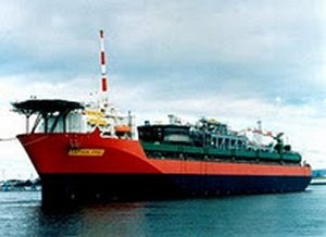
During a routine inspection on the Chevron-operated Captain floating production, storage and offloading vessel (FPSO), the company identified an integrity issue with one of the vessel’s eight fairleads – noting that one of the bolts connecting the gypsy wheel shaft to the skirt of the fairlead was missing. This identification reinforces the importance of Chevron’s rigorous maintenance, reliability and integrity procedures.
All fairleads on the Captain FPSO have since been been retrofitted with an axle pin retaining shaft, designed and supplied by Whittaker Engineering, which improve the overall integrity of the design.
Whittaker Engineering required a number of structural analyses to be conducted on the Fairlead design, to investigate the cause of a failure in the bolts and to evaluate the work that would be required to prolong the life of the Captain FPSO fairleads. FEA were performed on the original and retrofitted designs.
Analysis
 An FE model was created to investigate the cause of a failure in the bolts that hold the gypsy wheel axle to the fairlead skirts. A static non-linear (frictional contact and large deflection) solution was set up to evaluate the behaviour of the bolts and the resistance of the fairlead spindle to rotate.
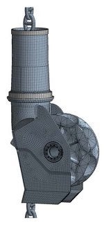
The geometry created in Autodesk Inventor, was imported into ANSYS DesignModeler for de-featuring and mesh preparation. The geometry featured the original design and the retrofitted gypsy wheel pin. During the course of the project the chain was also added into the FE model. The chain was modelled from its connection at the tensioner winch to the fairlead (about 40 links), and down through the spindle to the gypsy wheel, finishing at the last chain link that would possibly contact the fairlead skirt.
The models were meshed with high order 3D solid elements and non-linear frictional contacts were used to simulate the contact relationship between the individual chain links, the chain links and gypsy wheel and finally chain links and fairlead skirts. The welded connections were modelled as contact interfaces using a bonded behaviour. Two loading scenarios were analysed:
- Out of plane loading: the effect of an out of plane mooring chain force on the bolts and the moments needed to initiate the fairlead realignment (rotation of the fairlead to align itself with the mooring line direction)
- Chain Twist: the effects on the bolts of a 45° rotation / twist of the mooring chain
The original and retrofitted models were both analysed under the same two loading conditions with the aim of comparing the behaviour before and after the repair work.
The chain loadings were associated with a nominal condition in calm sea state determined by Chevron and provided for the analyses. The models were loaded in three stages with the first two stages being the same for both loading scenarios and the last stage distinguishing between the out of plane load and the chain twist, as follows:
- Initial tension of 95t was applied to the end half link of the chain in its straight configuration, and the bolts at the gypsy shaft were pre-stressed with a load of 75kN each
- The chain was forced to acquire its final in-plane configuration wrapping around the gypsy wheel with an angle to vertical of 30°
- Out of plane: the free end link of the chain was displaced out of plane, contacting and pushing sideways at the fairlead’s skirt
- Chain twist: the top end link of the chain was twisted 45° while the bottom end of the chain was fixed sideways
The chain was fully fixed at the top link and the fairlead was constrained at the ORKOT bearings, the external rings of the bearings were fully constrained and a frictional contact was defined between the spindle and the internal faces of the bearings, a 0.15 friction coefficient was used.
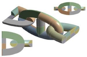
The mooring chain itself was also investigated in order to understand the torsional and bending stiffness behaviour of the chain. Models were created to evaluate the influence of the shape of the links and number of links in the chain. Both the torsional and bending stiffness investigations demonstrated non-linear behaviour that was very dependent on the geometry and number of links.
Out of plane load results
 The main focus of the analyses under this scenario was to understand the behaviour of the fairlead, in particular the load distribution on the gypsy wheel pin bolts under a lateral load cause by the sideways movement of the mooring chain.
Results on the original and retrofitted models, showed a significant resistance of the fairlead to rotate and therefore realign itself to the mooring line load, this resistance was causing one of the skirts to splay out adding extra load to the bolts under investigation.
There were two effects that contributed to this resistance: the friction force at the supports and the torsional resistance of the chain. It was found that most of the resistance came from the supports rather than the twist of the chain; this behaviour was found to be consistent on both models; original and retrofitted.
Due to the extra load going through the skirts the pretension given to the bolts was not enough to be maintained at its constant initial value and therefore could be subjected to a cyclic load that would possibly lead to fatigue problems. This load oscillation was more noticeable in the original model than in the retrofitted one. The bolt loads were compared on both models and it was found that the retrofitted model helped to reduce the loads on the bolts but they were still relatively high.
Chain twist results
The results showed that the twist of the chain affected the forces on the bolts; however these changes in force were quite small compared to the ones under a lateral load. Results for the original and retrofitted models showed similar results and the differences were found to be marginal.
Conclusion
The tension of 95t in the mooring chain and the relative location of the gypsy wheel to the supports generated high radial loads at the supports resulting in considerable frictional forces which prevented rotation of the fairlead. This high lateral load was found to damage the skirts of the fairlead and applied large loads to the gypsy wheel shaft bolts.
The large lateral load needed to force the rotation of the fairlead created a high load on a subset of the pin bolts, some of them reached stresses well above yield. The retrofitted model reduced the stress in the bolts to levels just below yield; however the pretension needed to prevent any cyclic load on the bolts would be very high reaching limits that were not acceptable.
Design benefit
The analysis showed the very likely cause of the bolts failure and also demonstrated that the retrofitted design would help to mitigate the problem but was not sufficient on its own. More importantly, the analysis gave a clear picture of the load transfer through the fairlead (from chain to the fairlead bearings) and how this load path drastically changed with out of plane loads. The knowledge acquired during this analysis not only provided a solution to a localised problem but helped improve the overall design – key lessons that are now transferable across the industry.